ETH484 - 4 Relays at 16A, 8 Digital IO and 4 Analogue Inputs
Tutti i prezzi sono IVA inclusa
E' PRESENTE UN PRODOTTO PIU' AGGIORNATO
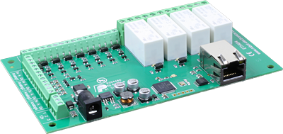
The ETH484 provides four volt free contact relay outputs with a current rating of up to 16Amp each, 8 digital I/O and 4 analogue inputs. The module is powered from a 12vdc supply which can be regulated or unregulated. The DC input jack is 2.1mm with positive core polarity, DC supplies are required to supply at least 500mA at 12vdc. The relays are SPCO (Single Pole Change Over) types. The normally open, normally closed and common pins are all available on the screw terminals.
A new feature has been added that allows the digital inputs to remotely control relays or digital outputs on ETH008, ETH484 or ETH8020. This offers the opportunity to construct a system where an input can control an output anywhere on the earth provided both locations are connected to the network/internet.
Operating Temperature
-40C to +70C
LED Indication
The ETH484 provides a red LED mounted immediately next to each relay to indicate whether it is in a powered state (LED on), there is also two LED's mounted in the Ethernet connector which will flash with Ethernet traffic. Finally there is a green power LED just above the processor.
Relay Power Rating
If the contact load voltage and current of the relay are in the region enclosed by the solid and dotted lines in the figure below, the relay can perform stable switching operation. If the relay is used at a voltage or current exceeding this region, the life of the contacts may be significantly shortened.
| load type | Typical applications | Rating | Max DC load capacity
|
| AC1 | Non inductive or slightly inductive loads |
16A @ 250V AC | |
| AC15 | Control of electromagnetic load (>72VA) |
3A @ 120V AC 1.5A @ 240V AC |
|
| AC3 | Control of motor | 750W | |
| DC1 | Non inductive or slightly inductive loads |
16A @ 24V DC | |
| DC13 | Control of electromagnetic loads |
0.22A @ 120V DC 0.1A @ 250V DC |

A full datasheet for the relays used on the ETH484 is here: HF115FD datasheet
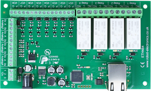
Connections
|
|
Digital I/O |
16A VFC (Volt Free Contacts) |
|
 |
|||
| Analogue inputs 5v = 5v dc output A = Analogue Input (0-3.3v) 0v = 0v ground |
|||
| 12v dc output Direct from 2.1mm jack |
|||
| 12v dc 2.1mm jack (+ve core) RJ45 Ethernet | |||
First Test
Having plugged in your 12vdc power supply and Ethernet connection, start up your web browser and type http://eth484 into the address bar, please note this only works in windows. You will be prompted for a password as shown below:
|
|
The default login is: Username: admin Password: password The ability to change these settings is shown in the configuration section |

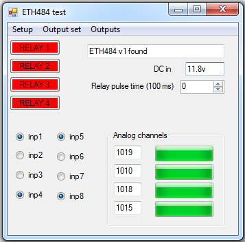
You should now see the following web page:

This web page will allow you to switch the relays on and off by clicking the relay buttons (the red/gray circles). It also contains a link to this technical documentation page.
Configuration
By clicking the configuration link it's possible to configure the ETH484 IP address and subnet mask together with the ability to set a password for entry to control screens. Gateway address and DNS address is configurable and is used with mapped inputs which are described in section below. The also offers the option to set a password that will be required to change any of the relay states or digital outputs using TCP IP commands, this is explained in the TCP/IP password section.
All settings are saved to memory so be careful to remember the username and password! Default password settings are shown in the picture below.

Mapped inputs
Digital inputs are able to be configured to remotely control outputs on ETH008,ETH484 or ETH8020, this offers simple linking and versatile usage. An input in one country can control a output in another, or across a small network.
There are eight independent inputs that can be mapped to eight different relays (on the same or different boards).
The "Address of target board" field accepts an IP address or hostname (which will be converted to an IP address by the DNS server supplied in the board configuration above). If the module is on the local network then you can use the
assigned IP address, if the target is over the internet then you need to supply the gateway in the configuration (internet source IP like your router) and the "Address of target board" is the IP address of the targets internet connection (to point at the router). Accessing the target via a router is dealt with in the section "Access from the Internet".

Factory Reset
Should it be necessary to reset the ETH484 to its shipped condition then the end two contacts of the row of 5 holes near the large chip on the side nearest the Ethernet connection must be shorted together at board power up. The green LED should then flash as the settings are reset, please wait until the LED finishes flashing and do not remove power during this period.
Firmware Updates
The firmware is fully updateable by re-flashing the board using our custom windows program. This will be made available in the event of feature updates.
ETH484 Command Set
The command set designed to provide consistent expansion and new features, they are sent over TCP/IP on port 17494 (0x4456). This is the default port, it can be changed in the configuration settings.
Five connections are allowed at any one time, these are independently protected but all using the same password as defined in the board configuration.
| Command |
Action |
|
| dec | hex | |
| 16 | 10 | Get Module Info - returns 3 bytes. Module Id (20 for ETH484), Hardware version, Firmware version. |
| 32 | 20 | Digital Active - follow with 1-4 to set relay on, or 9-16 for digital I/O then a time for pulsed output from 1-255 (100ms resolution) or 0 for permanent |
| 33 | 21 | Digital Inactive - follow with 1-4 to turn relay off, or 9-16 for digital I/O then a time for pulsed output from 1-255 (100ms resolution) or 0 for permanent |
| 35 | 23 | Digital Set Outputs - the first byte will set all relays states, All on = 255 (xxxx1111) All off = 0, 2nd byte sets digital outputs |
| 36 | 24 | Digital Get Outputs - returns 2 bytes, the first corresponds with relays being powered and the 2nd corresponds with active digital outputs |
| 37 | 25 | Digital Get Inputs - returns 2 bytes, the 1st is always 0 as the relays are not inputs, the 2nd bytes bits correspond with the digital io, a high bit meaning input is active (driven low) |
| 49 | 31 | Get Analogue Voltage - follow with 1-4 for channel and ETH484 will respond with 2 bytes to form an integer (high byte 1st) |
| 119 | 77 | Get Serial Number - Returns the unique 6 byte MAC address of the module. |
| 120 | 78 | Get Volts - returns relay supply voltage as byte, 125 being 12.5V DC |
| 121 | 79 | Password Entry - see TCP/IP password |
| 122 | 7A | Get Unlock Time - see section below |
| 123 | 7B | Log Out - immediately re-enables TCP/IP password protection |
Active and Inactive I/O - What do we mean by that?
Our Ethernet modules could potentially have many types of outputs. The ETH008 only has one type - Relays. The ETH484 has both Relay outputs and NPN Open Collector Transistor outputs. Activating a relay means turning the relay on. Likewise activating an output means turning the transistor on. This will cause it to sink current to 0v ground. If you had an LED connected from the output to 12v (via a resistor of course) it would light up. Other modules (not this one) could have PNP Open Collector Transistor outputs. These types will source current from the supply when active.
So here's the point: Active does not mean a high voltage comes out. It means that the output has been activated. That could result in the output sinking or sourcing current, depending on its type. The ETH484 outputs will sink current (up to 100mA) when active.
The same principle applies to the ETH484's inputs. These are designed to allow you to directly connect a VFC (Volt Free Contact). This could be from other relay contacts, thermostat contacts, alarm contacts etc. When the contacts are closed the input will read as active. In fact anything that pulls the input pin down to 0v will read as active. Do not think of the I/O in terms of a high or low voltage output. Think of it in terms of Active (or on, something is actively driving the I/O), or inactive (or off, nothing is driving the I/O).
It's a subtle point but one you need to be clear on.
Digital Active/Inactive Commands
These are 3 byte commands:
The first byte is the command, 32 (active means on) or 33 (inactive).
Second byte is the output number, 1-4 for the relays, or 9 - 16 for digital outputs (marked I/O1 to I/O8 on the board).
Third byte is the on time. Set this to zero for un-timed operation, or 1-255 for a pulse in 100mS intervals (100mS to 25.5 seconds).
For example:
0x20 - turn the relay on command
0x03 - relay 3
0x32 (50) - 5 seconds (50 * 100ms)
Note - All bytes in a command must be sent in one TCP/IP packet . Digital outputs pull the output pin down to 0v when active and pull up to 12v via a 10k resistor when inactive.
Digital inputs
Digital Inputs can be read with a command of 0x25. The two bytes returned will be encoded with each bit corresponding to whether the input is active or inactive. A high bit means the pin is either being pulled low (active) by the output or has an external device pulling low. To use the pins as inputs, the corresponding output must be made inactive. The first byte returned will always be zero. The 8 inputs are in the second byte.

Representative Digital I/O Schematic.
Analogue Inputs
Four analogue inputs of 0v-3.3V at 10-bit resolution are provided. The conversion is performed when you send the "Get Analogue Voltage" command 0x31 and the channel number. The resulting 16 bit integer will be transmitted back in two bytes (high byte first), combine these for the result. The 10-bit conversion will be in the lower 10 bits of the 16 bit integer with the upper 6 bits being 0. Note that although the analogue input voltage is 0-3.3v, there is a 5v supply available on the terminals. This is generally more useful as a supply for your own circuitry than 3.3v.

Representative Analogue Input Schematic.
TCP/IP Password
If this option is enabled in the http configuration page then a password will be required to be entered before relay states can be changed. In the following example the password was set to "apple":
0x79 - 1st byte in frame sent to ETH484 to indicate password entry
'a' (0x61) - 2nd byte in frame (ASCII hex equivalent in brackets, full table is available at http://www.asciitable.com/)
'p' (0x70) - 3rd byte in frame
'p' (0x70) - 4th byte in frame
'l' (0x6C) - 5th byte in frame
'e' (0x65) - 6th byte in frame
These 6 bytes are then transmitted in the same transaction to the ETH484 and if the password is correct then 1 will transmitted back, a failure will send 2.
The board will now accept changes from the device that entered the password. If communication becomes idle for more than 30 seconds then the password protection is re-enabled. There is also a log-out command of 0x7B to enable the protection immediately.
Get Unlock Time
Returns TCP/IP password protection status:
0 - password protection is enabled and password entry is required before changes can be made
1 to 30 - seconds until TCP/IP password protection is re-enabled. All authorised commands set the timer back to 30 seconds (including this one).
255 - TCP/IP password is not enabled.
IP Addresses & DHCP Servers
The easiest way to use the ETH484 is to connect it to a network with a DHCP server. In this case the ETH484 will have its IP address assigned automatically by the DHCP server.
If there is no DHCP server on the network, then a fixed IP address of 192.168.0.200 is used. To control the ETH484 using this fixed IP address your computer MUST be on the same subnet.
The next step is to set your computers IP address to 192.168.0.x where x is in the range of 1 to 255 but not 200 (the ETH484 is there!) or any other used IP addresses on the network.
The subnet mask dictates what IP addresses the PC can communicate with, we set this to 255.255.255.0 so the PC can talk to any module with an IP address of 192.168.0.x
The default gateway is likely to be the IP address that the internet connection is located at and the DNS server can be either your router address or google provide a DNS service at 8.8.8.8..
|

Test program and example source code
To get the ETH484 up and running in the minimum amount of time we have put together an example program to demonstrate the functionality of the module. We provide the full source code for this program. You may examine this code to see how it works or use it as a starting point for your own application.

Visual studio express C# examples
The test program is available as Visual C# express ready built installation files here, or as Visual C# express project with source files here.
Visual studio express is provided free from Microsoft: http://www.microsoft.com/exPress/download/
Access from the Internet
The ETH484 can be controlled over the internet almost as easily as on your local network. Your network will most likely be connected to the internet with a broadband router. This will provide NAT (Network Address Translation) and Firewall services. To access the ETH484 from the internet you will need to open up port 17494 (0x4456) to allow incoming TCP connections. Be careful not to open up any other ports. There are a wide variety of routers and we cannot give details for all of them. If in doubt ask your system administrator for assistance. The following shows how to open up a port on a Netgear DG834 router.

After logging on to your routers setup page, the first thing to do is create a new service. Click on the "Services" menu then "Add Custom Service". Enter a name for the service, select TCP and enter the ETH484's port address for both the start and finish ports. Click "Apply".

Now go to the "Firewall Rules" menu and click "Add" in the Inbound services section. Select the ETH484 service and ALLOW always. The "Send to LAN Server" IP address is the ETH484's IP address, 192.168.0.96 in the example above but check what it is on your network. Click "Apply" and that's it. The ETH484 is now accessible over the internet. Before you close the routers setup pages, go to the "Router Status" menu and make a note of its ADSL port IP address. This is the routers internet facing IP address.

To test this you will need a computer that has its own internet connection and is NOT connected to the same network as the ETH484. Download and run the test program above and select Custom IP. In the pop-up box enter your routers internet facing IP address. Click on "Try IP" and it will connect you to the ETH484 just as if it were on your own network.
Android & iPhone Apps.
We have a free app IO network available for Android and iPhone to remotely control your relays, download from Google Play or iTunes. Search for "Devantech" and you will find the app.
Board dimensions
