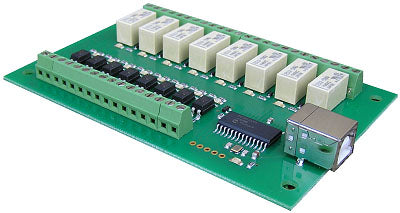
USB-OPTO-RLY88 - USB Module with 8 optoisolated inputs and 8 relay 1A
Tutti i prezzi sono IVA inclusa
Relays - 8
Isolated Inputs - 8
Power - Powered from standard USB bus
Control interface - USB
Input Voltage - 4.5v DC to 27v DC
Relay current - Up to 1Amp @30vdc or 60vac. 500mA@110vac. 250mA@250vac
Connections - Screw Terminals for N/O, N/C, Common contacts and +/- Inputs.
Full USB-OPTO-RLY88 Documentation
Examples:
Linux
Linux GCC - A command line tool that will set the relays and display input states
Linux with Mono and Xbuild (C#) - Simple example of switching the relays and displaying inputs
Mac
Xcode - Simple example of switching the relays and displaying inputs
Microsoft Windows
Visual C# Express - Simple example of switching the relays and displaying inputs
Visual Basic Express - Simple example of switching the relays and displaying inputs
Overview
The USB-OPTO-RLY88 provides eight optically isolated inputs and eight volt free contact relay outputs with a current rating of up to 1Amp each. It is powered from any standard USB bus and has an exceptionally low maximum current consumption of approx. 90mA with all relays on. The relays are SPCO (Single Pole Change Over) types. The normally open, normally closed and common pins are all available on the screw terminals.
|
Specification |
|
| USB - | Standard type B receptacle. |
| Inputs - | Absolute Max. 30v DC, Operational 4.5v to 27v DC |
| Outputs - | Relay Contacts, see power graph below |
LED Indication
Each of the eight input channels has a Green LED to indicate the input status.
Each relay output has a Red LED to indicate the relay status.
Also power status is indicated with an LED driven from the USB supply.
Commands
The USB-OPTO-RLY88 operates with an easy to use command set as described in the table below. Most commands are only a single byte and if applicable the USB-OPTO-RLY88 will automatically send its response. The only exception to this being the "Set relay states" command which requires and additional desired states byte to be sent immediately after the command byte.
| Command |
Action |
|
| dec | hex | |
| 17 | 11 | Returns channel 1 state as 1 byte, where 255 indicates input is powered and 0 indicates it is not. |
| 18 | 12 | Returns channel 2 state as 1 byte, where 255 indicates input is powered and 0 indicates it is not. |
| 19 | 13 | Returns channel 3 state as 1 byte, where 255 indicates input is powered and 0 indicates it is not. |
| 20 | 14 | Returns channel 4 state as 1 byte, where 255 indicates input is powered and 0 indicates it is not. |
| 21 | 15 | Returns channel 5 state as 1 byte, where 255 indicates input is powered and 0 indicates it is not. |
| 22 | 16 | Returns channel 6 state as 1 byte, where 255 indicates input is powered and 0 indicates it is not. |
| 23 | 17 | Returns channel 7 state as 1 byte, where 255 indicates input is powered and 0 indicates it is not. |
| 24 | 18 | Returns channel 8 state as 1 byte, where 255 indicates input is powered and 0 indicates it is not. |
| 25 | 19 | Sends 1 byte back. Individual bits indicate input status of each channel, a 1 indicating powered input |
| 26 | 1A | Sends 8 bytes back. First byte is channel 1 as per command 0x11 above. Last byte is channel 8. |
| 56 | 38 | Returns 8 ASCII characters. This is an 8-digit globally unique identifier. No two modules will share this. |
| 90 | 5A | Get software version - returns 2 bytes, the first being the Module ID which is 12, followed by the software version |
| 91 | 5B |
Get relay states - sends a single byte back to the controller, bit high meaning the corresponding relay is powered |
| 92 | 5C | Set relay states - the next single byte will set all relays states, All on = 255 (11111111) All off = 0 |
| 100 | 64 | All relays on |
| 101 | 65 | Turn relay 1 on |
| 102 | 66 | Turn relay 2 on |
| 103 | 67 | Turn relay 3 on |
| 104 | 68 | Turn relay 4 on |
| 105 | 69 | Turn relay 5 on |
| 106 | 6A | Turn relay 6 on |
| 107 | 6B | Turn relay 7 on |
| 108 | 6C | Turn relay 8 on |
| 110 | 6E | All relays off |
| 111 | 6F | Turn relay 1 off |
| 112 | 70 | Turn relay 2 off |
| 113 | 71 | Turn relay 3 off |
| 114 | 72 | Turn relay 4 off |
| 115 | 73 | Turn relay 5 off |
| 116 | 74 | Turn relay 6 off |
| 117 | 75 | Turn relay 7 off |
| 118 | 76 | Turn relay 8 off |
Opto Input Schematic
Test program and example source code
To get the USB-OPTO-RLY88 up and running in the minimum amount of time we have put together an example program to demonstrate the functionality of the module.

The test program is available built and ready to install here OptoRelayTest or as C# source code here OptoRelaySource
Board dimensions
