21 Servo Control Module
Tutti i prezzi sono IVA inclusa
| Technical Specifications : | |
| Voltage | Separate terminals or from servo supply when 7.2v battery is used |
| Number of Servo's | 21 |
| Refresh Rate | 20mS under all conditions |
| Control Interface | I2C |
| Microcontrollers | Picaxe-18x, BS2p, Atom or BX-24 can be fitted |
| Position Control | Directly programmed in us |
| Speed Control | From maximum down to 20 seconds for full rotation |
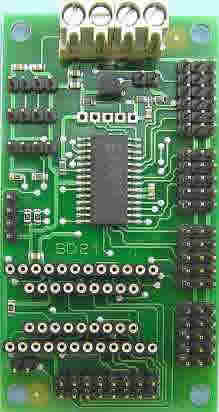
The SD21 is a 21 channel servo controller module. It will drive up to 21 RC servo's and maintain a 20mS refresh rate, regardless of the number of servo's used or their positions (pulse widths). It will control both position and speed of the servo's. It's controlled by sending commands to the on-board PIC18F2220 over the I2C bus. There are 3 I2C connectors on the board, any one of which can be used to connect to your controller. Alternatively, many controllers such as the Picaxe, BS2p, Atom, BX-24 etc. can be fitted directly to the module, making this a great animatronics controller.

Power
There are two ways to power the SD21. The first is to used a 5v supply for the processor section and a separate 6v-7.2v supply for the servo's. This is the recommend method, and the 4-way terminal block allows for this option. The logic and servo grounds are internally connected on the PCB. Not everyone wants to use two batteries, so we have allowed for the use of a single (typically 7.2v) battery to power the servo's and the module. To do this place a link on the two pin header below the terminal block. This routes servo power to a low drop 5v regulator which supplies the logic. The connections must be made to the servo terminals on the terminal block - NOT the logic ones. The SD21 monitors the servo battery voltage, which is available for reading from an internal register.
Servo's
The servo's are plugged directly onto the SD21, with the ground pin (black wire on a hitec servo) nearest the outside of the PCB.

Basic Stamp BS2p or compatible controller
A 24 pin socket on the SD21 will accept a BS2p or compatible controller such as the ATOM or BX-24. The Stamp is fitted with pin 1 nearest the outside of the module and away from the servo connectors. The BS2p P0(pin5)/P1(pin6) are used for the I2C SDA/SCL lines. These are the only I/O pins used on the module, the remainder are brought out on the 16 pin header, as shown above.
|
 |

Picaxe Controller
A 18 pin socket on the SD21 will accept the PICAXE-18X. Outputs 1 and 4 are used for I2C (they are the hardware I2C port on the PIC) and the remaining inputs and outputs are available on the 16 pin header. The Picaxe is fitted with pin 1 nearest the outside of the module and away from the servo connectors.
|
 |

Servo Processor
The heart of the SD21 is a pre-programmed PIC18F2220 chip. This is accessed over the I2C bus at address 0xC2 ($C2) by one of the controller options above, fitted to the module, or from an external controller connected to one of the I2C connectors. There are three internal registers associated with each of the 21 servo's. The speed and low byte/high byte of the position.
| Register | Servo | Function | Register | Servo | Function | Register | Servo | Function | ||
| 0 | 1 | Speed | 24 | 9 | Speed | 48 | 17 | Speed | ||
| 1 | 1 | Low byte | 25 | 9 | Low byte | 49 | 17 | Low byte | ||
| 2 | 1 | High byte | 26 | 9 | High byte | 50 | 17 | High byte | ||
| 3 | 2 | Speed | 27 | 10 | Speed | 51 | 18 | Speed | ||
| 4 | 2 | Low byte | 28 | 10 | Low byte | 52 | 18 | Low byte | ||
| 5 | 2 | High byte | 29 | 10 | High byte | 53 | 18 | High byte | ||
| 6 | 3 | Speed | 30 | 11 | Speed | 54 | 19 | Speed | ||
| 7 | 3 | Low byte | 31 | 11 | Low byte | 55 | 19 | Low byte | ||
| 8 | 3 | High byte | 32 | 11 | High byte | 56 | 19 | High byte | ||
| 9 | 4 | Speed | 33 | 12 | Speed | 57 | 20 | Speed | ||
| 10 | 4 | Low byte | 34 | 12 | Low byte | 58 | 20 | Low byte | ||
| 11 | 4 | High byte | 35 | 12 | High byte | 59 | 20 | High byte | ||
| 12 | 5 | Speed | 36 | 13 | Speed | 60 | 21 | Speed | ||
| 13 | 5 | Low byte | 37 | 13 | Low byte | 61 | 21 | Low byte | ||
| 14 | 5 | High byte | 38 | 13 | High byte | 62 | 21 | High byte | ||
| 15 | 6 | Speed | 39 | 14 | Speed | 63 | - | |||
| 16 | 6 | Low byte | 40 | 14 | Low byte | 64 | - | Software version | ||
| 17 | 6 | High byte | 41 | 14 | High byte | 65 | - | Battery Volts | ||
| 18 | 7 | Speed | 42 | 15 | Speed | |||||
| 19 | 7 | Low byte | 43 | 15 | Low byte | |||||
| 20 | 7 | High byte | 44 | 15 | High byte | |||||
| 21 | 8 | Speed | 45 | 16 | Speed | |||||
| 22 | 8 | Low byte | 46 | 16 | Low byte | |||||
| 23 | 8 | High byte | 47 | 16 | High byte |
Servo Position
The position (low byte/high byte) is a 16 bit number which directly sets the output pulse width in uS. Setting the position to 1500 (1500uS or 1.5mS) will set most servo's to their center position. The range of pulse widths that are normally supported are from 1000uS (1mS) to 2000uS (2mS). It is usually possible to go beyond these limits though. On a Hitec HS311 servo, we can set the position from 800 to 2200 to give a nice wide range of movement. Take care though as its easy to make the servo run into its internal stops if you give it pulse widths at the upper or lower extremes. The registers can also be read back. The position will be the current position of the servo during a speed controlled movement, so you can track its progress towards the requested position.
Servo Speed
The speed register controls the speed at which the servo moves to its new position. The servo pulses are automatically refreshed every 20mS. If the Speed register is zero (0x00) then the servo is simply set to the requested position. On power up the Speed registers are set to zero to give full speed, so unless you need to slow them down the Speed registers can be ignored. If the Speed register is set to something other than zero then that value is added to the current position every 20mS until the target position is reached. If you wish to move from 1000 to 2000 and the Speed register is set to 10, then it will take 2 seconds to reach the set position. The formula for the time it will take to make the move is:
((Target position-Start position)/Speed Reg)*20mS
Here are some examples:
| Start Position | Target Position | Speed Reg | Time for Move |
| 2000 | 1000 | 10 | 2000mS (2Sec) |
| 1000 | 2000 | 10 | 2000mS (2Sec) |
| 1000 | 2000 | 1 | 20000mS (20Sec) |
| 1000 | 2000 | 100 | 200mS (0.2Sec) |
| 1234 | 1987 | 69 | 220mS (0.22Sec) |
More Registers!
The servo's can be fully controlled by the above registers, however to make things easier for low resource controllers such as the Picaxe, there is another set of registers (63-83 inclusive). These can set the position by writing a single byte rather than two bytes. These are not physically implemented registers, so cannot be read back. When you write to them, the processor will multiply the number you write by 6 then add an offset of 732 and store the result in the real 16-bit registers described above. This gives you a range of 732 (0*6+732) to 2268 (256*6+732) in 6uS steps. This set of registers is called the Base set. The formula is:
Base Reg*6+732uS
Although you can't read them back, the data is stored internally, and used with another two sets of registers. These are positive (84-104) and negative (105-125) offsets. When you write to the positive offset address the processor will add it to the base position, multiply by 6 and add 732. It performs a similar function for negative offsets. the formulas are:
(BaseReg + PosReg) * 6 + 732 and
(BaseReg - NegReg) * 6 + 732
| Servo | Base Reg | Pos Offset Reg | Neg Offset Reg |
| 1 | 63 | 84 | 105 |
| 2 | 64 | 85 | 106 |
| 3 | 65 | 86 | 107 |
| 4 | 66 | 87 | 108 |
| 5 | 67 | 88 | 109 |
| 6 | 68 | 89 | 110 |
| 7 | 69 | 90 | 111 |
| 8 | 70 | 91 | 112 |
| 9 | 71 | 92 | 113 |
| 10 | 72 | 93 | 114 |
| 11 | 73 | 94 | 115 |
| 12 | 74 | 95 | 116 |
| 13 | 75 | 96 | 117 |
| 14 | 76 | 97 | 118 |
| 15 | 77 | 98 | 119 |
| 16 | 78 | 99 | 120 |
| 17 | 79 | 100 | 121 |
| 18 | 80 | 101 | 122 |
| 19 | 81 | 102 | 123 |
| 20 | 82 | 102 | 124 |
| 21 | 83 | 104 | 125 |
Register Summery
For precision control of the servo's there is the real 16-bit registers which sets the servo position directly in uS. For low resource controllers the servo's can be controlled by 8-bit values. The positive and negative offset registers make designing walking robots very easy where legs can be easily moved either side of a central position. We have examples of controlling a Lynxmotion EH2 robot with a BS2p Stamp using the 16-bit registers and the Picaxe doing the same using the 8-bit Base and Offset registers.
Software Revision Number
Register 64 is the software revision number (3 at the time of writing this).
Battery Voltage
Register 65 contains the servo battery voltage in 39mV units up to a maximum of 10v. A battery voltage of 7.2v will read about 184. 6v will read about 154. It is updated every 20mS whether its read or not.
Address
The SD21 Servo module is located at address 0xC2 on the I2C bus.
Example Code
This shows how to use a BS2p Stamp to control a servo. It sets up a simple loop which sends the servo between two positions
| '{$STAMP BS2p} SDA CON 0 ' SDA on pin0, SCL on pin1 SD21 CON $C2 ' SD21 I2C address Servo1 CON 0 ' register address of servo1 speed reg (followed by pos low/pos high) Speed CON 0 ' maximum speed Servo1p CON 1800 ' Right position Servo1n CON 1200 ' Left position Servo VAR W0 Loop: Servo = Servo1p I2COUT SDA, SD21, Servo1, [Speed, Servo.LOWBYTE, Servo.HIGHBYTE] PAUSE 300 Servo = Servo1n I2COUT SDA, SD21, Servo1, [Speed, Servo.LOWBYTE, Servo.HIGHBYTE] PAUSE 300 GOTO Loop |
This does the same for the Picaxe controller using the alternative register set.
| Servo1 = 63 ' servo 1 base register Servo1p = 84 ' servo 1 positive offset register Servo1n = 105 ' servo 1 negative offset register Base = 128 ' centre position Offset = 50 ' +/- 50 from centre position ProgStart: |