Dettagli
Modulo pilotabile tramite porta USB, e' ideale per progetti di Animatronics e ovunque sia necessario controllare un grande numero di servi e servizi accessori, include anche porte ADC a 10-bit di risoluzione.
| Canali Servo |
- |
fino a 84 |
| Porte Logiche Output | - | fino a 84 |
| Porte Logiche Input | - | fino a 84 |
| Porte Analogiche 10-bit | - | fino a 36 |
| Refresh rate dei servi | - | 20ms in ogni condizione |
| Controllo Posizione | - | Programmata direttamente in uS |
| Controllo Velocita' | - | Regolabile dalla velocita' massima fino a 20 secondi per una rotazione continua |
| Alimentazione Logica | - | Dal Bus USB |
| Alimentazione Servi | - | A discrezione dell'Utente, in gruppi da 8 servi, disponibili i terminali a vite |
| Interfaccia di controllo | - | USB |
Overview
The SD84 is an 84 channel servo controller module. It will drive up to 84 RC servo's and maintain a 20mS refresh rate, regardless of the number of servo's used or their positions (pulse widths). It controls both the speed and position of the servo's. It's controlled by sending commands to the on-board processors over the USB bus. Each of the 84 channels can be a Digital Input, Digital Output or Servo Output. Additionally, 36 of the channels can be 10-bit Analogue inputs, making this a great animatronics controller.
Features
Up to 84 channels of digital inputs.
Up to 84 channels of digital outputs.
Up to 84 channels of servo outputs.
Up to 36 channels of 10-bit analogue inputs.
Controlled and Powered from the USB bus.
Drivers available for Windows, Apple, Linux and Open BSD.

Connection Diagram of the SD84
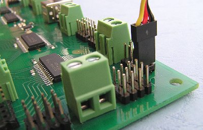
The SD84 has 84 sets of 3-pin headers, in groups of 4 at a time. In all cases, the pin nearest the outside of the PCB is 0v Ground. The middle pin is +V power for the servo from the associated 2-pin screw terminals. The inside pin, nearest the CPU's is the signal pin.
Power
The logic circuitry on the SD84 module is powered from the USB bus and does not require any external power. You need to provide external power for the servo's or any other circuitry you want to connect to the I/O's. The servo's are powered in groups of 8 servo's. PL1 provides the power for servo's 1 to 8 on ch1 to ch8. The only exception is PL5 which powers 12 servo's ch33 to ch44 inclusive. The bar lines on the diagram above indicate which servo's are powered from which screw terminals. Each group can be powered from a different voltage, but note that the 0v grounds are all common and connected together on the PCB.
Connecting Servo's
The servo's are plugged directly onto the SD84, with the ground pin (black wire on a hitec servo) nearest the outside of the PCB.
First Step - Get The Drivers
The SD84 module uses the FTDI FT232R USB chip to handle all the USB protocols. The documentation provided by FTDI is very complete, and is not duplicated here. Before using the SD84, you will need to install FTDI's Virtual COM Port ( VCP ) Drivers. These drivers appear to the system as an extra Com Port ( in addition to any existing hardware Com Ports ). Application software accesses the USB device in the same way as it would access a standard Windows Com Port using the Windows VCOMM API calls or by using a Com Port Library. Drivers are available for Windows, Apple, Linux and Open BSD systems directly from the FTDI website. You should get and install the drivers now, before you connect the SD84 to your computer. The Drivers page is here.
Which COM port?
After installing the drivers, and plugging in the SD84 module to a spare USB port, you will want to know which COM port it has been assigned to. This will vary from system to system depending on how many COM ports you currently have installed. To find out where it is with Windows98, right click on your "My Computer" desktop icon and select the "Device Manager" tab. Now scroll down and open the "Ports (COM & LPT)" tab. You should see the USB serial port listed - COM2 in the example below. If you want to change the COM port number - just right click on it, select properties, select advanced and select the COM port number from the available list. With Windows XP, select "Start", then right click "My computer", then select "Properties", then the "Device Manager" tab.
The COM port should be set up for 115200 baud, 8 data bits, no parity and two stop bits.

With the drivers installed you can now connect the SD84 and Windows will register the drivers.
Internal Registers
There are three internal registers associated with each of the 84 channels.
A "Mode" register (1 Byte) that defines the current mode of the channel, INPUT, OUTPUT_LOW, OUTPUT_HIGH, SERVO or ANALOGUE.
A "Servo" register (2 Bytes) that defines the position of the servo in uS. The "Servo" register is an integer (two bytes). The speed and low byte/high byte of the position.
A "Speed" register (1 Byte) that defines the speed that the servo's change position.
Commands
| Dec | Hex | Command | Description | Response |
| 1 | 0x01 | SET_SERVO | Sets the position (in uS) of 1 to 84 servo's | 1 Byte, error code - see Error Codes |
| 2 | 0x02 | GET_SERVO | Returns the current position (in uS) of a single servo | 2 Bytes, Servo Position, Low byte first, then the high byte. |
| 3 | 0x03 | SET_SPEED | Sets the movement speed of 1 to 84 servo's | 1 Byte, error code - see Error Codes |
| 4 | 0x04 | SET_MODE | Sets the mode of 1 to 84 channels, not analogue - see SET AD CNT command. |
1 Byte, error code - see Error Codes |
| 5 | 0x05 | GET_MODE | Returns the current mode of a single channel | 1 Byte, Mode - see Channel modes |
| 6 | 0x06 | SET_AD_CNT | Set the number of analogue channels from 0 to 36. This also sets the Mode for the channel to Analogue |
1 Byte, error code - see Error Codes |
| 7 | 0x07 | GET_AD_CNT | Returns the number of analogue channels currently set. | 1 Byte, Number of analogue channels. |
| 8 | 0x08 | GET_INPUT | Returns the status of a single input | 1 Byte, 0x00 for low, 0xFF for high |
| 9 | 0x09 | GET_ADC | Returns the current value of a single analogue channel | 2 Bytes, low byte first, then the high byte |
| 10 | 0x0A | GET_VERSION | Returns version number of the selected processor chip (1 to 4) | 2 Bytes, Module type first, then version number |
| 21 | 0x15 | GET_BULK | Used for Factory Testing - returns 21 encoded inputs | 3 Bytes, all 21 inputs on selected CPU |
| 22 | 0x16 | TEST | Used for Factory Testing - |
SET_SERVO (0x01)
This command sets the position of the servos in uS. Normal range for a servo is 1000uS to 2000uS with 1500uS being the center position. Most servo's will go beyond this though. On a Hitec HS422 servo, we can set the position from 800 to 2200 to give a nice wide range of movement. Take care though as its easy to make the servo run into its internal stops if you give it pulse widths at the upper or lower extremes. The SD84 places no restrictions on the value written, so be careful. Each servo value is a 16-bit integer, sent low byte first, then the high byte. To set ch1 to 1500uS (Center the servo) The command format is:
| Sync1 | Sync2 | Sync3 | Command | First Channel | Byte Count | Low Byte | High Byte |
| 0xAA | 0xA0 | 0x55 | 0x01 | 0x01 | 0x02 | 0xDC | 0x05 |
The first three bytes are synchronization bytes and are required by all command frames.
Next is the SET_SERVO command 0x01.
Next is the First Servo channel number. In this case channel 1.
Next is the byte count. 2 bytes per channel for servo position setting.
Next is the low byte of the position. 1500 decimal is 0x05DC in hex, so we send 0xDC.
Finally we send the high byte, 0x05
Any number of contiguous channels can be set with one SET_SERVO command. For example to set channels 37 and 38 to 1000uS (0x03E8) and 2000uS (0x07D0), you would send:
| Sync1 | Sync2 | Sync3 | Command | First Channel | Byte Count | Ch37 low byte | Ch37 high byte | Ch38 low byte | Ch38 high byte |
| 0xAA | 0xA0 | 0x55 | 0x01 | 37 | 4 | 0xE8 | 0x03 | 0xD0 | 0x07 |
If you wanted to do the same for channels 37 and 51, you would have to send two command frames. You could not do it all in one frame because the channels are not contiguous.
After the final byte is sent, the SD84 will reply with a single byte error code. If all is well this will be OK. See error codes for details.
GET_SERVO (0x02)
This command gets the position of the servo in uS.
| Sync1 | Sync2 | Sync3 | Command | Channel | Byte Count |
| 0xAA | 0xA0 | 0x55 | 0x02 | 23 |
0x00 |
The above example will return the position of servo channel 23. Note the byte count must be zero (0x00) because you are not sending any data to the SD84. The response from the SD84 will be two bytes, low byte first, then the high byte. For example if you had set the position to 1500uS (0x05DC in hex) you would receive 0xDC, 0x05.
Unlike the SET_SERVO command, GET_SERVO can only work with a single channel. To retrieve the position of multiple channels you must get them individually.
SET_SPEED (0x03)
Sets the speed the servo's will move to the new positions.
| Sync1 | Sync2 | Sync3 | Command | First Channel | Byte Count | Speed |
| 0xAA | 0xA0 | 0x55 | 0x03 | 71 | 1 | 10 |
The above example would set ch71 speed to 10.
The speed register controls the speed at which the servo moves to its new position. The servo pulses are automatically refreshed every 20mS. If the Speed register is zero (0x00) then the servo is simply set to the requested position. On power up the Speed registers are set to zero to give full speed, so unless you need to slow them down the Speed registers can be ignored. If the Speed register is set to something other than zero then that value is added to the current position every 20mS until the target position is reached. If you wish to move from 1000 to 2000 and the Speed register is set to 10, then it will take 2 seconds to reach the set position. The formula for the time it will take to make the move is:
((Target position-Start position)/Speed Reg)*20mS
Here are some examples:
| Start Position | Target Position | Speed Reg | Time for Move |
| 2000 | 1000 | 10 | 2000mS (2Sec) |
| 1000 | 2000 | 10 | 2000mS (2Sec) |
| 1000 | 2000 |
1 |
20000mS (20Sec) |
| 1000 | 2000 | 100 | 200mS (0.2Sec) |
| 1234 | 1987 | 69 | 220mS (0.22Sec) |
As with the SET_SERVO command, the SET_SPEED command can set up to 84 channels.
| Sync1 | Sync2 | Sync3 | Command | First Channel | Byte Count | Speed1 | Speed2 | Speed3 |
| 0xAA | 0xA0 | 0x55 | 0x03 | 71 | 3 | 9 | 10 | 11 |
The above example would set ch71 speed to 9, ch72 speed to 10 and ch73 speed to 11. Don't forget to make sure the byte count is the same as the number of data bytes being sent, 3 bytes in this example.
SET_MODE (0x04)
This command is used to set the Mode of up to 84 channels. Note! this command cannot select or deselect Analogue mode, you must use the SET_AD_CNT to do that. The reason for this is explained in the SET_AD_CNT section. This command will select between INPUT, OUTPUT_LOW, OUTPUT_HIGH or SERVO modes. See Channel Modes for details.
The following example will set ch1 to INPUT_MODE, ch2 to OUTPUT_MODE0, ch3 to OUTPUT_MODE1 and ch4 to SERVO_MODE.
| Sync1 | Sync2 | Sync3 | Command | First Channel | Byte Count | Mode1 | Mode2 | Mode3 | Mode4 |
| 0xAA | 0xA0 | 0x55 | 0x04 | 1 | 4 | 23 | 21 | 22 | 25 |
As always, make sure the byte count matches the amount of data bytes your sending. After the final byte is sent, the SD84 will reply with a single byte error code. If all is well this will be OK. See error codes for details.
GET_MODE (0x05)
This command gets the current MODE of a single channel. See Channel Modes.
| Sync1 | Sync2 | Sync3 | Command | Channel | Byte Count |
| 0xAA | 0xA0 | 0x55 | 0x05 | 15 |
0x00 |
The above example will return the current mode of channel 15. Note the byte count must be zero (0x00) because you are not sending any data to the SD84. The response from the SD84 will be 1 byte which is the mode. Unlike the SET_MODE command, GET_MODE can only work with a single channel. To retrieve the current mode of multiple channels you must get them individually.
SET_AD_CNT (0x06)
This command sets the number of analogue channels available. The SD84 uses 4 PIC18F2520 processor chips, each providing 21 channels of which 9 can alternatively be analogue inputs. These 9 analogue channels appear scattered around on the SD84, see the connection diagram at the top of this page, because the pin numbers on the processor on which they appear is fixed. A limitation of the processor chip is that these pins cannot randomly be analogue inputs, they have to be assigned in order, starting at AN1. If AN8 is Analogue then so must AN1 to AN7. You can see then, that changing a channel to analogue can potentially also change a number of other channels. This is why writing to the Mode register to change to or from analogue mode is prevented.
The SET_AD_CNT command configures the processor chips for the requested number of analogue channels, starting with AN1. If you select 5 analogue channels then it is AN1 to AN5 that are analogue. The Mode register for channels 21, 22, 20, 18 and 28 will be set to analogue. These are the channels that AN1 to AN5 appear on. If you had previously selected 10 analogue channels (AN1 to AN10) and then select 5 (AN1 to AN5) then channels 27, 29, 26, 30 and 11 (AN6 - AN10) will be changed back to digital and will be Inputs.
Analogue and Digital Channels Cross Reference.
| AN | CH | AN | CH | AN | CH | AN | CH | |||
| 1 | 21 | 10 | 11 | 19 | 84 | 28 | 73 | |||
| 2 | 22 | 11 | 10 | 20 | 83 | 29 | 72 | |||
| 3 | 20 | 12 | 9 | 21 | 82 | 30 | 71 | |||
| 4 | 18 | 13 | 7 | 22 | 80 | 31 | 69 | |||
| 5 | 28 | 14 | 38 | 23 | 48 | 32 | 58 | |||
| 6 | 27 | 15 | 37 | 24 | 47 | 33 | 57 | |||
| 7 | 29 | 16 | 39 | 25 | 49 | 34 | 59 | |||
| 8 | 26 | 17 | 36 | 26 | 46 | 35 | 56 | |||
| 9 | 30 | 18 | 40 | 27 | 50 | 36 | 60 |
To set the number of analogue channels use the following command:
| Sync1 | Sync2 | Sync3 | Command | Channel | Byte Count | Analogue Count |
| 0xAA | 0xA0 | 0x55 | 0x06 | 0 (ignored) | 1 | 10 |
The above command will set AN1 to AN10 as analogue inputs. The Mode of the corresponding Channels 21, 22, 20, 18, 28, 27, 29, 26, 30 and 11 will be set to ANALOG_MODE.
The SD84 will reply with a single byte error code. If all is well this will be OK. See error codes for details.
The normal initialization procedure would be to first set the number of analogue channel required by using the SET_AD_CNT command, and then set the remaining digital channels to input, output or servo modes as required. This can be done for all channels with a single mode command. The analogue channels will not be affected by the Mode command so it does not matter what they are set to, however you will get a WARNING code returned instead of the OK code.
GET_AD_CNT (0x07)
This command returns the quantity of analogue channels currently selected.
| Sync1 | Sync2 | Sync3 | Command | Channel | Byte Count |
| 0xAA | 0xA0 | 0x55 | 0x07 | 0 (ignored) | 0 |
The SD84 will respond with the current analogue channel count, 0 - 36.
GET_INPUT (0x08)
Returns the status of the single selected input channel.
| Sync1 | Sync2 | Sync3 | Command | Channel | Byte Count |
| 0xAA | 0xA0 | 0x55 | 0x08 | 12 | 0 |
The above example will return 1 Byte, 0 (0x00) if the input on channel 12 is low or 255 (0xFF) if the input is high. GET_INPUT can only work with a single channel. To retrieve the status of multiple channels you must get them individually.
GET_ADC (0x09)
Returns the analogue value of the selected channel. Note the Channel number is the AN analogue number, not the digital channel number. In the example below this is AN21-CH82.
| Sync1 | Sync2 | Sync3 | Command | Channel | Byte Count |
| 0xAA | 0xA0 | 0x55 | 0x09 | 21 | 0 |
Analogue inputs are converted on demand. The above example will return 2 Bytes, low byte first then the high byte. The SD84 uses 10-bit AD conversion so you will get a number in the range 0-1023. Results are only valid for analogue channels that have previously been set to analogue mode using the SET_AD_CNT command.
GET_VERSION (0x0A)
This command is used to return the firmware version number for the SD84. There are 4 CPU's on the SD84 and you can specify which CPU you want the version number from - they will all be the same.
| Sync1 | Sync2 | Sync3 | Command | CPU Number | Byte Count |
| 0xAA | 0xA0 | 0x55 | 0x0A | 2 | 0 |
The command format is shown above. In this example the version number from CPU2 will be returned. The command returns 2 bytes. The first is the module type, this will always be 84 for the SD84. The second byte is the firmware revision number, currently 4 at the time of writing. Valid CPU Numbers are 1-4.
GET_BULK (0x15)
This command is used for factory testing of the SD84. It is potentially useful though, and so is documented here. It returns 3 bytes which encode all 21 inputs for the selected processor. If you are familiar with the PIC processors, these 3 bytes are ports A, B, and C (in that order). The command format is:
| Sync1 | Sync2 | Sync3 | Command | CPU Number | Byte Count |
| 0xAA | 0xA0 | 0x55 | 0x15 | 1 | 0 |
In this example the 3 bytes will come from CPU1. Valid CPU Numbers are 1-4.
The table below shows which channel each bit represents.
| Byte 1 - PortA | Byte 2 - PortB | Byte 3 - PortC | ||||||||||||||||||||||
| 7 | 6 | 5 | 4 | 3 | 2 | 1 | 0 | 7 | 6 | 5 | 4 | 3 | 2 | 1 | 0 | 7 | 6 | 5 | 4 | 3 | 2 | 1 | 0 | |
| CPU1 | 17 | 16 | 18 | 19 | 20 | 22 | 21 | x | 23 | 24 | 25 | 26 | 27 | 28 | 29 | 30 | x | x | 31 | 32 | 12 | 13 | 14 | 15 |
| CPU2 | 6 | 5 | 7 | 8 | 9 | 10 | 11 | x | 33 | 34 | 35 | 36 | 37 | 38 | 39 | 40 | x | x | 41 | 42 | 1 | 2 | 3 | 4 |
| CPU3 | 79 | 78 | 80 | 81 | 82 | 83 | 84 | x | 43 | 44 | 45 | 46 | 47 | 48 | 49 | 50 | x | x | 51 | 52 | 74 | 75 | 76 | 77 |
| CPU4 | 68 | 67 | 69 | 70 | 71 | 72 | 73 | x | 53 | 54 | 55 | 56 | 57 | 58 | 59 | 60 | x | x | 61 | 62 | 64 | 63 | 65 | 66 |
The bit will be high if the input is high.
TEST (0x16)
This command is used, together with GET_BULK documented above, for factory testing of the SD84. It is of no other use, but documented here for the sake of completeness.
| Sync1 | Sync2 | Sync3 | Command | Channel | Byte Count |
| 0xAA | 0xA0 | 0x55 | 0x16 | 67 | 0 |
It first sets the number of analogue channels to zero, so everything is digital.
It then sets every channel to drive low (OUTPUT_MODE0).
It then sets every channel to input (INPUT_MODE).
It then sets the selected channel to drive high (OUTPUT_MODE1).
And finally returns code OK. The sequence is performed without any delays, as fast as the processors will go.
Channel Modes
Available modes for the channels are:
| Decimal | Hex | Mode | Description |
| 21 | 0x15 | OUTPUT_MODE0 | Output low, Logic 0 |
| 22 | 0x16 | OUTPUT_MODE1 | Output High, Logic 1 |
| 23 | 0x17 | INPUT_MODE | Can read High or Low |
| 24 | 0x18 | ANALOG_MODE | Can read 0-1023 (10-bit conversion) |
| 25 | 0x19 | SERVO_MODE | Outputs servo pulse, 20mS repetition rate. |
Error Codes
The SD84 can reply with the following possible error codes.
| Decimal | Hex | Error Code | Description |
| 0 | 0x00 | OK | Command processed OK |
| 1 | 0x01 | WARNING | Attempt to change to or from Analogue mode by writing to mode register is ignored. |
| 2 | 0x02 | RANGE | Range of channels is less than 1 or more than 84. |
| 3 | 0x03 | MODE | Unknown Mode received |
Demonstration Program
We have a small demonstration program to allow you to quickly evaluate the SD84.

It allows you to set the number of analogue channels, set modes, move servo's and read digital or analogue inputs. The program is written in Visual C++ V6. You can download just the sd84.exe or the complete source code.
SD84 PCB Drilling Plan
Questions on Servo Controller Multifunzione a 84 Canali
No questions asked yet
Fai una domanda (Registrati oppure Esegui il Login ).|
3412 - 3-Channel Wide FOV Time-of-Flight Distance Sensor Using OPT3101 (No Headers) 
Tasse escluse:
€ 29,90
IVA inclusa:
€ 36,48
|

Tasse escluse:
€ 16,50
IVA inclusa:
€ 20,13
|
-
191065 1065_1B - PhidgetMotorControl 1-...
 Tasse escluse:€ 87,50IVA inclusa:€ 106,75
Non ci sono prodotti da comparare
-

-

-
 1354 - Mini Maestro 18-Channel USB Servo Controller (Assembled)
Tasse escluse:€ 34,54IVA inclusa:€ 42,14 -


