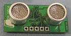
Miniature Ultrasonic Range Finder
Tutti i prezzi sono IVA inclusa
| Technical Specifications : | |
| Voltage | 5V |
| Current | 15mA - 3mA Standby |
| Frequency | 40 Khz |
| Range | 3cm - 6mt |
| Max Analogue Gain | Variable 40 to 700 in 16 steps |
| Units | Range reported in uS, mm or inches |
| Connection | Protocollo I2C |
| Dimensions | 32 x 15 x H 10 mm |
Introduction
Communication with the SRF10 ultrasonic rangefinder is via the I2C bus. This is available on popular controllers such as the OOPic and Stamp BS2p, as well as a wide variety of micro-controllers. To the programmer the SRF10 behaves in the same way as the ubiquitous 24xx series eeprom's, except that the I2C address is different. The default shipped address of the SRF10 is 0xE0. It can be changed by the user to any of 16 addresses E0, E2, E4, E6, E8, EA, EC, EE, F0, F2, F4, F6, F8, FA, FC or FE, therefore up to 16 sonar's can be used. We have examples of using the SRF10 module with a wide range of popular controllers.
Connections
The connections to the SRF10 are identical to the SRF08. The "Do Not Connect" pin should be left unconnected. It is actually the CPU MCLR line and is used once only in our workshop to program the PIC16F87 on-board after assembly, and has an internal pull-up resistor. The SCL and SDA lines should each have a pull-up resistor to +5v somewhere on the I2C bus. You only need one pair of resistors, not a pair for every module. They are normally located with the bus master rather than the slaves. The SRF10 is always a slave - never a bus master. If you need them, I recommend 1.8k resistors. Some modules such as the OOPic already have pull-up resistors and you do not need to add any more.

Registers
The SRF10 appears as a set of 4 registers.
| Location | Read | Write |
0 |
Software Revision |
Command Register |
1 |
Unused (reads 0x80) |
Max Gain Register (default 16) |
2 |
Range High Byte |
Range Register (default 255) |
3 |
Range Low Byte |
N/A |
Only locations 0, 1 and 2 can be written to. Location 0 is the command register and is used to start a ranging session. It cannot be read. Reading from location 0 returns the SRF10 software revision. By default, the ranging lasts for 65mS, but can be changed by writing to the range register at location 2. The SRF10 will not respond to commands on the I2C bus whilst it is ranging. See the Changing Range and Analogue Gain sections below.
Locations, 2 and 3, are the 16bit unsigned result from the latest ranging - high byte first. The meaning of this value depends on the command used, and is either the range in inches, or the range in cm or the flight time in uS. A value of 0 indicates that no objects were detected.
Commands
The are three commands to initiate a ranging (80 to 82), to return the result in inches, centimeters or microseconds. There is also a set of commands to change the I2C address.
| Command | Action | |
| Decimal | Hex | |
| 80 | 0x50 | Ranging Mode - Result in inches |
| 81 | 0x51 | Ranging Mode - Result in centimeters |
| 82 | 0x52 | Ranging Mode - Result in micro-seconds |
| 160 | 0xA0 | 1st in sequence to change I2C address |
| 165 | 0xA5 | 3rd in sequence to change I2C address |
| 170 | 0xAA | 2nd in sequence to change I2C address |
Ranging Mode
To initiate a ranging, write one of the above commands to the command register and wait the required amount of time for completion and read the result. The echo buffer is cleared at the start of each ranging. The default and recommended time for completion of ranging is 65mS, however you can shorten this by writing to the range register before issuing a ranging command.
Checking for Completion of Ranging
You do not have to use a timer on your own controller to wait for ranging to finish. You can take advantage of the fact that the SRF10 will not respond to any I2C activity whilst ranging. Therefore, if you try to read from the SRF10 (we use the software revision number a location 0) then you will get 255 (0xFF) whilst ranging. This is because the I2C data line (SDA) is pulled high if nothing is driving it. As soon as the ranging is complete the SRF10 will again respond to the I2C bus, so just keep reading the register until its not 255 (0xFF) anymore. You can then read the sonar data. Your controller can take advantage of this to perform other tasks while the SRF10 is ranging.
Changing the Range
The maximum range of the SRF10 is set by an internal timer. By default, this is 65mS or the equivalent of 11 metres of range. This is much further than the 6 metres the SRF10 is actually capable of. It is possible to reduce the time the SRF10 listens for an echo, and hence the range, by writing to the range register at location 2. The range can be set in steps of about 43mm (0.043m or 1.68 inches) up to 11 metres.
The range is ((Range Register x 43mm) + 43mm) so setting the Range Register to 0 (0x00) gives a maximum range of 43mm. Setting the Range Register to 1 (0x01) gives a maximum range of 86mm. More usefully, 24 (0x18) gives a range of 1 metre and 93 (0x5D) is 4 metres. Setting 255 (0xFF) gives the original 11 metres (255 x 43 + 43 is 11008mm). There are two reasons you may wish to reduce the range.
1. To get at the range information quicker
2. To be able to fire the SRF10 at a faster rate.
If you only wish to get at the range information a bit sooner and will continue to fire the SRF10 at 65ms of slower, then all will be well. However if you wish to fire the SRF10 at a faster rate than 65mS, you will definitely need to reduce the gain - see next section.
The range is set to maximum every time the SRF10 is powered-up. If you need a different range, change it once as part of your system initialization code.
Analogue Gain
The analogue gain register sets the Maximum gain of the analogue stages. To set the maximum gain, just write one of these values to the gain register at location 1. During a ranging, the analogue gain starts off at its minimum value of 40. This is increased at approx. 96uS intervals up to the maximum gain setting, set by register 1. Maximum possible gain is reached after about 100mm (4inches) of range. The purpose of providing a limit to the maximum gain is to allow you to fire the sonar more rapidly than 65mS. Since the ranging can be very short, a new ranging can be initiated as soon as the previous range data has been read. A potential hazard with this is that the second ranging may pick up a distant echo returning from the previous "ping", give a false result of a close by object when there is none. To reduce this possibility, the maximum gain can be reduced to limit the modules sensitivity to the weaker distant echo, whilst still able to detect close by objects. The maximum gain setting is stored only in the CPU's RAM and is initialized to maximum on power-up, so if you only want do a ranging every 65mS, or longer, you can ignore the Range and Gain Registers. The Gain Register is set to 16 (a gain of 700) at power-up. This can be decreased as required.
| Gain Register | Maximum Analogue Gain | |
| Decimal | Hex | |
| 0 | 0x00 | Set Maximum Analogue Gain to 40 |
| 1 | 0x01 | As above - Analogue Gain to 40 |
| 2 | 0x02 | Set Maximum Analogue Gain to 50 |
| 3 | 0x03 | Set Maximum Analogue Gain to 60 |
| 4 | 0x04 | Set Maximum Analogue Gain to 70 |
| 5 | 0x05 | Set Maximum Analogue Gain to 80 |
| 6 | 0x06 | Set Maximum Analogue Gain to 100 |
| 7 | 0x07 | Set Maximum Analogue Gain to 120 |
| 8 | 0x08 | Set Maximum Analogue Gain to 140 |
| 9 | 0x09 | Set Maximum Analogue Gain to 200 |
| 10 | 0x0A | Set Maximum Analogue Gain to 250 |
| 11 | 0x0B | Set Maximum Analogue Gain to 300 |
| 12 | 0x0C | Set Maximum Analogue Gain to 350 |
| 13 | 0x0D | Set Maximum Analogue Gain to 400 |
| 14 | 0x0E | Set Maximum Analogue Gain to 500 |
| 15 | 0x0F | Set Maximum Analogue Gain to 600 |
| 16 | 0x10 | Set Maximum Analogue Gain to 700 |
Note that the relationship between the Gain Register setting and the actual gain is not a linear one. Also there is no magic formula to say "use this gain setting with that range setting". It depends on the size, shape and material of the object and what else is around in the room. Try playing with different settings until you get the result you want. If you appear to get false readings, it may be echo's from previous "pings", try going back to firing the SRF10 every 65mS or longer (slower).
If you are in any doubt about the Range and Gain Registers, remember they are automatically set by the SRF10 to their default values when it is powered-up. You can ignore and forget about them and the SRF10 will work fine, detecting objects up to 6 metres away every 65mS or slower.
LED
The red LED is used to flash out a code for the I2C address on power-up (see below). It also gives a brief flash during the "ping" whilst ranging.
Changing the I2C Bus Address
To change the I2C address of the SRF10 you must have only one sonar on the bus. Write the 3 sequence commands in the correct order followed by the address. Example; to change the address of a sonar currently at 0xE0 (the default shipped address) to 0xF2, write the following to address 0xE0; (0xA0, 0xAA, 0xA5, 0xF2 ). These commands must be sent in the correct sequence to change the I2C address, additionally, No other command may be issued in the middle of the sequence. The sequence must be sent to the command register at location 0, which means 4 separate write transactions on the I2C bus. When done, you should label the sonar with its address, however if you do forget, just power it up without sending any commands. The SRF10 will flash its address out on the LED. One long flash followed by a number of shorter flashes indicating its address. The flashing is terminated immediately on sending a command the SRF10.
| Address | Long Flash | Short flashes | |
| Decimal | Hex | ||
| 224 | E0 | 1 | 0 |
| 226 | E2 | 1 | 1 |
| 228 | E4 | 1 | 2 |
| 230 | E6 | 1 | 3 |
| 232 | E8 | 1 | 4 |
| 234 | EA | 1 | 5 |
| 236 | EC | 1 | 6 |
| 238 | EE | 1 | 7 |
| 240 | F0 | 1 | 8 |
| 242 | F2 | 1 | 9 |
| 244 | F4 | 1 | 10 |
| 246 | F6 | 1 | 11 |
| 248 | F8 | 1 | 12 |
| 250 | FA | 1 | 13 |
| 252 | FC | 1 | 14 |
| 254 | FE | 1 | 15 |
Take care not to set more than one sonar to the same address, there will be a bus collision and very unpredictable results.
Changing beam pattern and beam width
You can't! This is a question which crops up regularly, however there is no easy way to reduce or change the beam width that I'm aware of. The beam pattern of the SRF10 is conical with the width of the beam being a function of the surface area of the transducers and is fixed. It is possible to make the sonar less sensitive to objects off to the side by reducing the maximum gain register from 16 to a lower level. This is a the expense of shorter range, however most small robots don't need 6m of range. A value of 8 (max. gain 140) will reduce the practicable range to about 2m, but it will be much less sensitive to objects off the center line. The beam pattern of the transducers used on the SRF10, taken from the manufacturers data sheet, is shown below.

There is more information in the sonar faq.
Mounting the SRF10
You may have notice that there are no mounting holes on the SRF10 module! That was deliberate to keep the module as small as possible. So how do you mount it? Here are three suggestions:
1. A straight or right angle 0.1 inch connector soldered to your PCB.
2. Using two 9.5mm rubber grommets. Two holes should be drilled into the panel you're mounting the SRF10 to. The hole centers should be 0.7inches (17.78mm) apart and the holes drilled 0.5 inches (12.7mm) in diameter. The two grommets should then be fitted to the panel and the SRF10 gently pushed into them.
3. Using our SRF10 Mounting Kit, shown below.
 |
 |