SRF01 Ultrasonic range finder
Tutti i prezzi sono IVA inclusa
| Technical Specifications : | |
| Voltage | 3,3 .... 5,5V |
| Current | 11mA (25mA during ranging) |
| Frequency | 40 Khz |
| Range | 18cm - 6mt (0cm - 600cm calibration required) |
| Data Interface | Serial TTL Signal |
| Bus | Up to 16 SRF01 on same bus |
| Units | CM or INCHES |
| Weight | 2,7 grams |
The SRF01 is a single transducer ultrasonic rangefinder in a very small footprint PCB. Connection is to a single pin Serial interface. The serial interface is a standard TTL level UART format of 1 start, 1 stop and no parity bits, and may be connected directly to many controllers, such as the Basic Stamps or the PICAXE. Baud rate at power-up is always 9600, there is a command to change this to 19200 or 38400 baud if preferred. Up to 16 SRF01's may be connected together on a single bus. Like all our rangefinders, the SRF01 can measure in Cm or Inches.
Power Requirements
The SRF01 accepts any voltage between 3.3v and 12v, however the recommended
maximum is 5.5v. Internally, it operates at
3.3v and there is a low dropout regulator already on the SRF01 to provide this.
The serial I/O pin operates at 3.3v and also 5v tolerant, so you can connect it directly to
3.3v or 5v signals. Operating current during ranging is 25mA, 11mA in standby
(waiting for a command) and around 55uA in sleep mode (shutdown).
Single Pin Serial Communication
Serial data is 1 start, 1 stop and no parity bits. Serial data is a TTL level
signal - It is NOT RS232. Do not connect the SRF01 to an RS232 port - you will
destroy the module! Communication with the SRF01 is with both serial input and
serial output on a single pin. The SRF01 will be listening at all times except
when it is actually sending data, and will go back to listening as soon as its
finished. To communicate with the SRF01, you simply need to send a
"break", followed by two bytes, the address of the SRF01 (factory
default is 1) and the command. A "break" is just a low level for 12
bit times or longer. 1.5mS or more will be fine. It is used to synchronize transfers on the 1-wire serial
bus. The default shipped address can be changed by the user
to any of 16 addresses 1, 2, 3, 4, 5, 6, 7, 8, 9, 10, 11, 12, 13, 14, 15 or 16,
and therefore up to 16 sonar's can be used. Note - this range is different to
the SRF02 which has addresses 0-15. The reason is that for specific commands
only all SRF01's regardless of their programmed address, will respond to
address 0. This makes it easy to start all SRF01s ranging at the same time.
Baud Rate
The serial baud rate on the SRF01 always starts at 9600 on power up. It can be
changed to 19200 or 38400 if you wish. It will revert to 9600 at the next power
up. To change the baud rate, just send a "break" followed by the
general call address of zero (not the module address), then command 0x64 for 19200 or command
0x65 for 38400. You can only send the command to address zero to change all
SRF01's at the same time.
Connections
The connections to the SRF01 are shown below. If you're using multiple SRF01's,
you can connect them all up to the same serial port on your controller. Just
make sure all the SRF01's are programmed to different addresses. There is a weak
pull-up resistor (47k) to 3.3v on the module, to pull the Tx line up to a logic
high level when none of the SRF01's are transmitting.

Commands
To send a command to the SRF01, you need to send a "break" followed by
two bytes. The first is the SRF01's address 1 to 16, (0x01 to 0x10) and then the
actual command itself - see below. There are two commands to initiate a ranging
(80 to 81) giving results in inches and centimeters. These two commands
don't Transmit the result back to your controller. You should wait 70mS and then use
command 94 to get the result of the ranging. Another set of two commands (83 to
84) do the same, but also transmits the result of the ranging back to your
controller as soon as it is available. Together, these four commands (80,81,84
& 84) are called "Real" because they perform a complete ranging.
There is another set of four commands (86, 87, 89 & 90) called
"Fake". They are the same as the "Real" commands except that
they do not send the 8-cycle ultrasonic burst out. These are used where the burst has been
transmitted by another sonar. It is up to you to synchronize the commands to the
two sonar's. There is a command (92) to transmit a burst without doing the
ranging.
Command 93 is used to get the firmware revision of the SRF01.
Command 94 gets returns two bytes (high byte first) from the most recent
ranging. Put them together to make a 16-bit result.
Command 95 gets the status byte. Bit 0 is the "Lock" bit. it is low (0)
after power up, after the "Unlock" command is executed and after the
module exits sleep mode. It goes high after 6 rangings have been completed with
at least 30cm of free space in front of the sonar. See Advanced
Mode for more details.
Command 96 is used to place the SRF01 in a low power sleep mode. See Sleep
Mode for more details.
Commands 98 & 99 are used to enable/disable Advanced Mode.
| Command | Address 0 Access | Action | |
| Decimal | Hex | ||
| 80 | 0x50 | Yes | Real Ranging Mode - Result in inches |
| 81 | 0x51 | Yes | Real Ranging Mode - Result in centimeters |
| 83 | 0x53 | No | Real Ranging Mode - Result in inches, automatically Tx range back to controller as soon as ranging is complete. |
| 84 | 0x54 | No | Real Ranging Mode - Result in centimeters, automatically Tx range back to controller as soon as ranging is complete. |
| 86 | 0x56 | Yes | Fake Ranging Mode - Result in inches |
| 87 | 0x57 | Yes | Fake Ranging Mode - Result in centimeters |
| 89 | 0x59 | No | Fake Ranging Mode - Result in inches, automatically Tx range back to controller as soon as ranging is complete. |
| 90 | 0x5A | No | Fake Ranging Mode - Result in centimeters, automatically Tx range back to controller as soon as ranging is complete. |
| 92 | 0x5C | Yes | Transmit an 8 cycle 40khz burst - no ranging takes place |
| 93 | 0x5D | No | Get software version - sends a single byte back to the controller |
| 94 | 0x5E | No | Get Range, returns two bytes (high byte first) from the most recent ranging. |
| 95 | 0x5F | No | Get Status, returns a single byte. Bit 0 indicates "Transducer locked", Bit 1 indicates "Advanced Mode" |
| 96 | 0x60 | Yes | Sleep, shuts down the SRF01 so that it uses very low power (55uA). |
| 97 | 0x61 | Yes | Unlock. Causes the SRF01 to release and re-acquire its "Transducer lock". Used by our factory test routines. |
| 98 | 0x62 | Yes | Set Advanced Mode (Factory default) - When locked, SRF01 will range down to zero. |
| 99 | 0x63 | Yes | Clear Advanced Mode - SRF01 will range down to approx. 12cm/5in, |
| 100 | 0x64 | Yes | Changes the baud rate to 19200 |
| 101 | 0x65 | Yes | Changes the baud rate to 38400 |
| 160 | 0xA0 | No | 1st in sequence to change I2C address |
| 165 | 0xA5 | No | 3rd in sequence to change I2C address |
| 170 | 0xAA | No | 2nd in sequence to change I2C address |
None of the commands which return data can use address 0. That
would mean SRF01's trying to transmit data at the same time, and is prevented.
Most commands which do not return data are allowed to use address 0. Exceptions
are address
change commands.
The advantage of allowing address 0 access is that by sending a ranging command
such as 0x51 (81 decimal), all SRF01s will start ranging at the same time. After
70mS, you can then get the results from each SRF01 at its own address.
LED
The Led gives a brief flash during the "ping" whilst ranging. If the
transducer has not locked, the Led is on with a brief flash off. If the
transducer is locked, the Led is off with a brief flash on.
If you power up the SRF01 without sending any commands, it will flash its
address out on the LED. One long flash followed by a number of shorter flashes
indicating its address. The flashing is terminated immediately on sending a
command sequence to the SRF01.
| Address | Long Flash | Short flashes | |
| Decimal | Hex | ||
| 1 | 01 | 1 | 0 |
| 2 | 02 | 1 | 1 |
| 3 | 03 | 1 | 2 |
| 4 | 04 | 1 | 3 |
| 5 | 05 | 1 | 4 |
| 6 | 06 | 1 | 5 |
| 7 | 07 | 1 | 6 |
| 8 | 08 | 1 | 7 |
| 9 | 09 | 1 | 8 |
| 10 | 0A | 1 | 9 |
| 11 | 0B | 1 | 10 |
| 12 | 0C | 1 | 11 |
| 13 | 0D | 1 | 12 |
| 13 | 0E | 1 | 13 |
| 15 | 0F | 1 | 14 |
| 16 | 10 | 1 | 15 |
Changing the SRF01 Address
To change the address of the SRF01 you must have only one sonar connected. Write
the sequence of three commands in the correct order followed by the address. Example;
to change the address of a sonar currently at 1 (the default shipped address) to
5, write the following to address 1; (0xA0, 0xAA, 0xA5, 0x05 ). These commands
must be sent in the correct sequence to change the address, additionally, No
other command may be issued in the middle of the sequence. The sequence must be
sent as four separate commands to the current address of the sonar. i.e.
"break" 0x01,
0xA0 then "break" 0x01, 0xAA, then "break" 0x01, 0xA5 and finally
"break" 0x01, 0x05. When done, you
should label the sonar with its new address. Take care not to set more than one
sonar to the same address, there will be a bus collision and very unpredictable
results. The new address is stored in flash memory on the SRF01 and will remain,
even if power is removed, until deliberately changed.
Standard Mode
In standard mode the SRF01 measures from approx 18cm (7 inches) to 600cm (19ft).
It requires no calibration or tuning to achieve this range. Standard mode is
recommended for commercial applications where the requirements of advanced mode
cannot be met. To set standard mode send the Clear Advanced Mode command, 99
decimal or 0x63.
Advanced Mode
This is the factory default mode. In this mode it is possible for the SRF01 to measure range all
the way down to zero.
Initially, the minimum range the SRF01 can detect is around 18cm or 7 inches. For the SRF01
to be able to measure all the way down to 0cm, it acquires a precision crystal lock on
the transducer's characteristics. This happens after 5 rangings have been
completed with 30cm or more of free space in front of the sensor. When this
happens the "lock" bit is set (bit 0 in the status byte) and the SRF01
can measure from 0 to 600cm (0-6meters).
During operation the SRF01 maintains the transducer lock automatically, provided it gets an occasional (every few minutes) set of 5 consecutive rangings of greater than 30cm. The "lock" state of the SRF01 can be checked in by reading the "Lock" bit, which is bit 0 in the status register. A high (or logic 1) indicates transducer lock has been achieved and the SRF01 will work down to 0cm. Where the SRF01 is not able to maintain its lock, it will release it (lock bit = zero) and re-acquire it as soon as possible.
Sleep Mode
When placed in sleep mode, all activity on the SRF01's processor ceases. The
module shuts down and power consumption is reduced to a minimum. This is just a
combination of quiescent current in the regulator and leakage current of the
processor. Typically 55uA. To wake the SRF01 up from sleep mode send 0xFF. Don't
send anything else - no "break", no address, because the 0xFF byte is
not a command, it's really just a single transition on the Rx line that wakes up
all SRF01's on the serial bus. After waking up the SRF01, you should wait 2mS
for the processor clocks to stabilise before sending commands.
Testing
|
|
 |

We have a small test program, written in C# which controls the
SRF01 via the Acroname
S22 module. A small schottky diode is used to prevent the SRF01 trying to
drive the S22's output line (data from the PC). You will need to download and
install the FTDI VCP drivers to use the
S22.
The complete
project directory, with all source files, can be downloaded
here. To use this
program you should download and install Microsoft
Visual C# 2008.
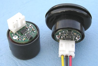
Mounting the SRF01
A rubber grommet is supplied to mount the SRF01. To use this make a 20mm cutout
in your panel and fit the grommet. The SRF01 will then snuggly push into the
hole in the grommet. Maximum panel thickness is 1.7mm.

Examples
Further examples of using the SRF01 can be found on our examples
page.